Below are some photos of the realizations made by you:
Realization of Dr. Daniele Bucciarelli
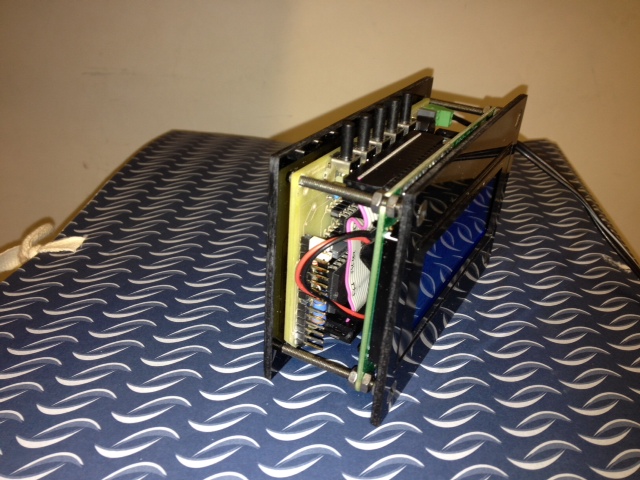
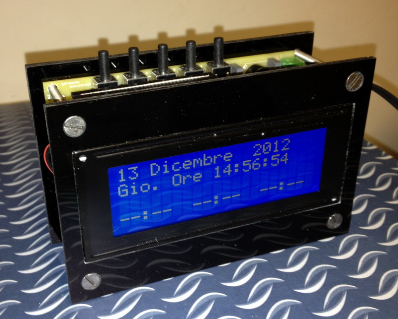
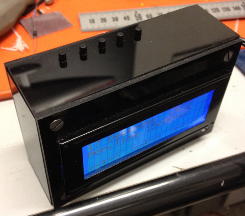
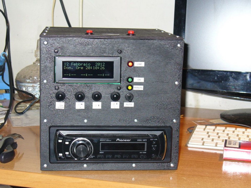
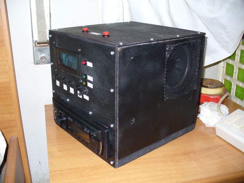
Realization of David Bettin
The changes are
described below:
I used to drive the design of Tony the ignition of a car that I was
advancing due to shift to higher model with integrated Bluetooth.
The radio is a Pioneer DEH-1120MP but you can employ any.
The PCB made of Tony scheme has the following changes:
- Elimination of the backup battery 3V, since I added a sealed lead acid
battery (the ones from car alarms) 12V, to keep the memories of the car and
have full functionality even in case of power failure;
- Elimination of buzzer, LED 1Hz and sync header for RS232 because I did not
need;
- Addition of a transistor and a small relay for the subkey on pin RA4 of
PIC (output common to all the alarms);
- Two buttons to snooze instead of one, to have twice as likely to peck one
throwing the hand in the dark :)
- Added an ICSP header, since the MCLR pin of the pic is pull-upped, you
must insert a diode, with the anode immediately after the 10K resistor and
the cathode on pin 1 of the PIC, which is then connected directly to the
relevant
pin header, otherwise with 13V paid when programming the pic, you risk doing
damage to the rest of the components.
The VCC pin header is isolated for the same reason, so hold power to the
circuit during programming.
No problem for the DATA and CLOCK pin (40 and 39 of the pic), as they are
not used in the schema.
- Use of a simple quartz oscillator instead IQX0 used by Tony for the pic,
while for the RTC oscillator was maintained DS32.
If you want to use a 10MHz quartz is imperative to remember to set the flag
HS on your programming software, before programming the pic.
Do not set the classic XT as not working, the frequency is too high.
At the code level I had to take action on '. Hex because the timeout of 120
seconds posted by Tony the alarms did not go well for my purposes.
Not having the source I could not do anything but delete the line that
decreases the record, I do not remember what is in memory, but you can get
there with a minimum of knowledge of the assembler and looking for the
register that stores the value 0x78, which is
just 120 in hexadecimal.
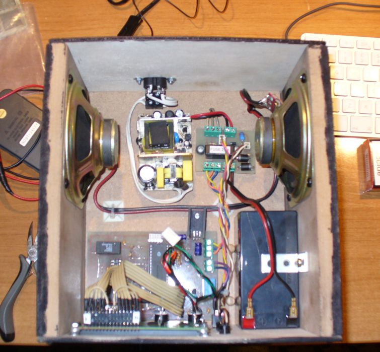
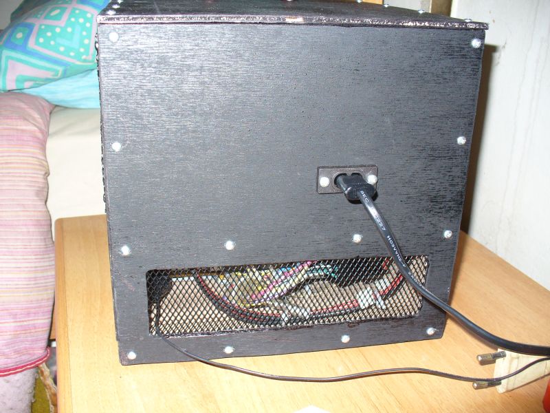
The box is made of MDF 16 mm, except for the front, rear and above, Plywood
4 mm.
Inside there is a 14V 3A switching power supply that feeds the whole, a
Fiamm battery 12V 1.2Ah and two speakers recovery from 8 ohms impedance.
The small pcb side of the power supply contains a limiting resistor to a
trickle charge the battery, two diodes 6A bypass between the power supply
and battery, a 2.5A fuse for safety put between the battery (or power
supply) and load,
and the headers for the three LEDs on the front, which from top to bottom
are "line" (power, it turns off when it passes in battery), "on" (lights up
when there is tension on the subkey), "manual
"(lights up together with" on "when you operate the switch on the front,
which is simply put in parallel between the contacts of the relay).
I do not have the pattern of this because I designed the PCB jet, then
attach two files FidoCAD.
The
first (R2) is what I used, with two headers.
The second (R3) I drew later and contains a header only; circuitly are
identical.
Do not attach the file. Fcd on the main board because it contains a design
error which I noticed only at the end, I solved the steering wheel with a
jumper but still do not have it redesigned.
I hope to be exhaustive, they are still available for further clarification.
FidoCad file powerboard R2-PER STAMPA PCB.rar
FidoCad file powerboard R3.rar
Davide Bettin bettindavide@gmail.com
The content of these pages was released for teaching applications WITHOUT end of I make money from. For any other type of application it be able to contact me via email.
© Copyright tony@microt.it