Schema elettrico - Electric diagram
Clock
with LCD and
PIC 18F4620
This is the introductory page of the clock with PIC 18F4620
Press the button in the upper left to access the latest version.
A special thanks to Daniele Bucciarelli
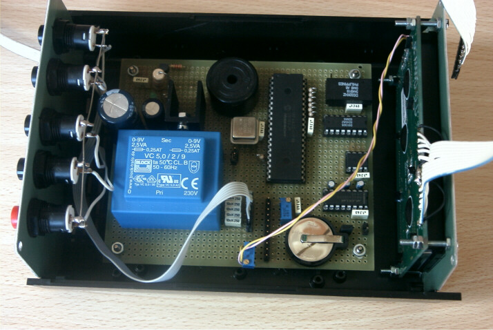
Thanks to its valuable work, will be available soon on printed circuit board (PCB) for the assembly of this watch and ... there will be other news.
Anyone wishing to contact him can write here: daniele@microt.it
Summary of technical characteristics
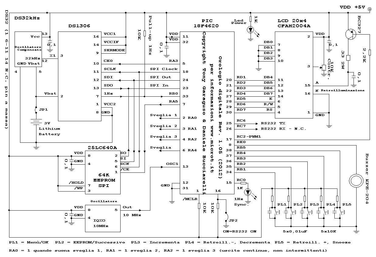
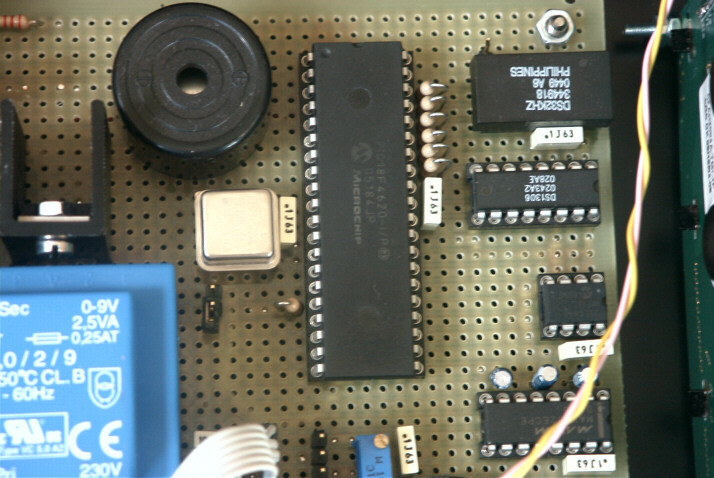
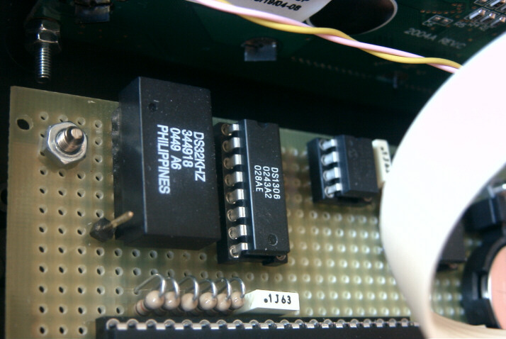
The excellent accuracy of the clock is given by the oscillator temperature compensated DS32KHZ the datasheet shows max + /-1min year with temperature ranging from 0 to 40 ° C and max + /-4min year with temperature ranging from -40 to +85 ° C. This watch has three independent alarms, and each alarm can be set in the following ways:
Every day, that is, when you turn off the alarm clock, the same is already preset for the next day. Only once, ie when you turn off the alarm clock, the same remains off. Mon to Fri, the alarm will sound at the set time every day from Monday to Friday, without having ever to touch, this alarm will not sound during the weekend (Saturday and Sunday). Mon to Sat, this alarm clock is similar to the previous one but for the unlucky ones who have to be up at the same time also on Saturday, so this alarm will not sound only on Sunday. In the case of overlapping hours played between alarms, among them there is a priority that alarm 1, alarm 2 then 3 and finally alarm, the alarm 1 is the left in the display, followed by the alarm from the alarm clock in the center and 2 to 3 right. The outputs available for the alarm clocks are the following: The buzzer which has an output intermittent, or to pin 6 (RA4) is a fixed output at logic 1 for the duration of the played and applies to all three clocks, or pin 2 (RA0) for alarm 1, pin 3 (RA1) for the alarm 2 and pin 4 (RA2) for the alarm 3. All of these outputs are logic 1 during play or snooze. Remain fixed at logic 1 in order to drive circuits DAST, digital radios etc. ... I think this is comprehensive management of alarm clocks but ... if anyone has more advice please let me know.
When an alarm sounds, it can be switched off using the PL1 or PL5 using the button, you can activate the snooze function (nap) which will sound the alarm again exactly 10 minutes later. When the alarm will sound, you can turn it off via the button as before PL1 or PL5 again with the Snooze button, this cycle can be repeated indefinitely.
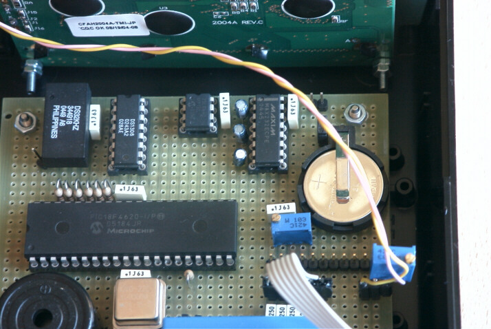
The brightness of the LCD display can be adjusted in 10 steps so that it is possible to have a good brightness of day and night and do not mind. This watch is equipped with an external eeprom to the micro that can store up to 255 events including holidays and birthdays can handle up to 3 events displayed in succession on the same day. E 'equipped with a 3V lithium battery that serves as a backup to the DS1306 which is the built-in clock, the battery lasts about 10 years. When there is a mains voltage, the clock will turn off but the alarm clocks and counting the hours continue without any problem. The only thing is that in this condition it is not possible to display the time and the alarm will not sound because the micro is not powered. The clock DS1306 contains an internal RAM area where the data is stored alarm clocks more a matter of control, just in case the battery is removed or is discharged and the data in the RAM are no longer valid when the watch is reenergized a function checks that the data contained in the ram of the DS1306 are valid otherwise forces the user to set the calendar, clock and alarm clocks. It 'also a LED (optional) reporting the sync clock to 1Hz. This watch also has a serial output RS232 (optional) which transmits the current time and date display with a mark to be able to synchronize any other equipment.
When alarms do not sound button PL1 need to enter the main menu and as OK in the confirmation menu choices, PL2 to enter the menu management birthdays and parties of the eeprom and to move "to the next" in the menu, the button PL3 increases, PL4 button decreases the display backlighting and decrements in the menus, the button backlight of the display increases the PL5 and while it sounds an alarm activates the snooze.
15/06/2011 version 1.04 has been released and contains the following changes:
Several times I have been asked to change the segment clock alarms, and so in addition to the intermittent buzzer that has an output, I added an out at fixed output, this out as the buzzer is common to all three alarm clocks. Having other out available I also added three out independent always fixed output. These fixed output out to have the highest level during the play.
Have been added in order to allow you to eliminate the buzzer and possibly add other circuits such as the DAST as an alarm clock, radio chips etc ...
Clearly, this version also includes changes to the 1.03 version that solves the problem of writing on External EEPROM, the eeprom attention is the type 25LC640A NOT 25LC640 is important because the SPI interface of the model 25LC640A of up to 10MHz.
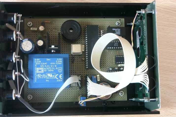
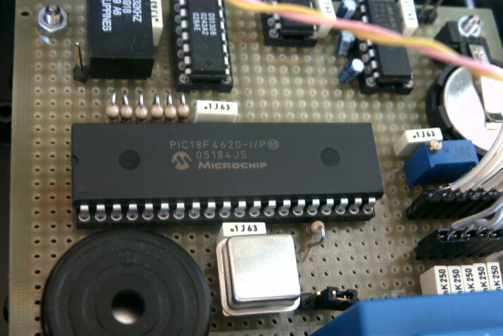
Given the excellent results obtained with the design of the previous clock with LCD driven by PIC 16F877A, I thought I'd replace the switch, and go to the PIC18 family well with 32K of memory and without the use of tables and pages.
The operation is similar to the previous clock made with PIC 16F877A because this micro despite being much more powerful is pin to pin with the previous year. See the specifications of the clock with PIC 16F877A
Changes:
1) The administration of the LCD backlight has been a PWM available inside the micro so by pressing the button to decrease the brightness PL4 and PL5 is increased by pressing the button. Pressing these buttons on line 3 of the display shows a scale from minimum to maximum indicating the current level of brightness after 10 seconds returns to normal operation.
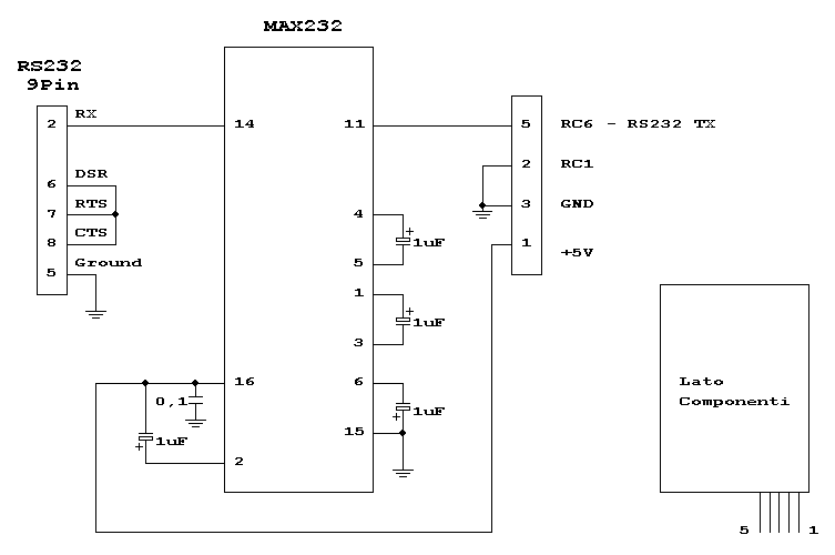
2) if jumper JP2 is inserted enables transmission via RS232 serial port, else the routine is ignored.
3) For the choice was maintained exterior plywood from 10MHz oscillator (more accurately), although because of the tolerance was possible to use the internal oscillator of the PIC 18F4620 by changing only a few routine timing.
Using the EEPROM:
Using
external EEPROM 25LC640
65536 Bit 8192x8 and organized into 32-byte page
8192:32 = 256 between birthdays and parties
The 32-byte page is so used:
|
1 |
2 |
3 |
4 |
5 |
6 |
7 |
8 |
9 |
10 |
11 |
12 |
13 |
14 |
15 |
16 |
|
Prog |
G |
M |
AH |
AL |
Flag |
|
|
|
|
|
|
Name |
|||
|
17 |
18 |
19 |
20 |
21 |
22 |
23 |
24 |
25 |
26 |
27 |
28 |
29 |
30 |
31 |
32 |
|
Continues name or party |
|||||||||||||||
Progressive Sequence Number = 0 ~ 255
G = Day
M = Month
AH = Top Half of the Year
AL = Bottom Half of the Year
Flag = 1=Birthday, 0=Party
Name = 20 characters to describe the party or write the name of the person's birthday.
Flow management EEPROM:
From the clock mode, you enter the menu by pressing PL2 management EEPROM passing through the following functions.
Check if the EEPROM is properly formatted, and if so, jump to menu 1
If the EEPROM is not formatted, it displays the Format menu / Cancel PL2 and pressing back the clock because you can not continue with the EEPROM not formatted, PL1 pressing the EEPROM is formatted and go to the menu 1
Menu1: Pressing the button PL2 returns to clock mode, pressing the button PL1 you enter the display mode EEPROM pages.
After pressing the button PL1, you see the page 00 of the EEPROM and you have three options, PL1 increments the address of the EEPROM and displays the next page, PL2 comes back to clock mode, PL3 enters edit the current page.
Entering have edit all five buttons with the following functions:
PL1 View the exit menu
PL2 Select the character / group of characters following / s for editing
PL3 Increases the value selected
PL4 Decreases the selected value
PL5 Deletes the current record
If the button is pressed PL1, appears the exit menu with choices:
PL1 Cancel and rereads
PL2 Save
If the button is pressed PL5, the menu appears with the following choices:
PL1 Cancel
PL2 Delete
Detail of the transmission via serial RS232:
* = Marker sync.
Italian Version:
12345678901234567890123456789012345678901234
* 25 Aprile 2005 - Lun Ore 11:23:03
English version:
123456789012345678901234567890123456789012345
* 25 April 2005 - Mon Time 11:14:47
© Copyright tony@microt.it