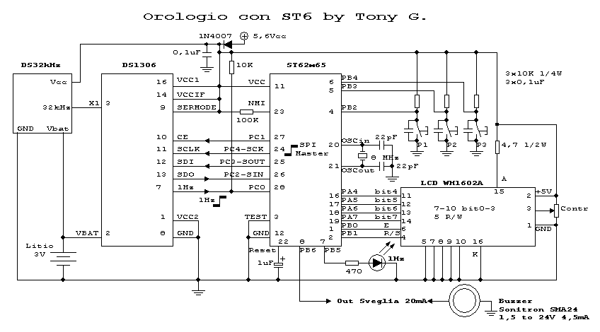
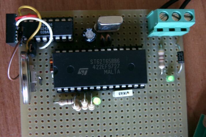
Clock with LCD and ST6
 

ATTENTION: Who created this or other projects on this web site, please can send me on my email photos of his accomplishments? I would like to put it here on-line so that they are visible and can serve as a starting point for new ideas, different realizations or changes, following in this way the spirit of this site which is in favor of disclosure and knowledge of electronics free of charge.
Also, if you, while sending photos of your prototypes, authorize me to put on-line together with the photos at least your name and your email, you will be contacted or you can contact another user who made the same project in order to do together of constructive confrontation.
Thank you in advance, Tony


Introction:
Making a clock that is satisfyingly precise seems an easy thing especially using a microprocessor. Over the years I have made ​​several watches and alarm clocks encountering several difficulties, for example, in drawing up the program a microcontroller ST6, more precisely ST62x65, I did several tests using the timer, the timer Auto charging and finally executing routines calculated, the latter , have the great inconvenience of having to be "adjusted" (most of the times experimentally) with various delays to obtain the greatest possible precision. A second problem is the black out, when there is no supply voltage the clock is reset, this presents a significant problem if you trust your watch to wake up, for example. This problem can be solved only with a battery backup of a certain size.

These solutions I did not like, and after various efforts, I forced myself to use in combination with an integrated all'ST6 chosen ad hoc with the functions of clock, calendar, alarm clock, and not less, a ram memory whose content is protected by the black out as for the clock, relatively simple to interface with the ST6 and so I decided to use the chip produced by Dallas / Maxim DS1306 which is a RTC (Real Time clock) interfaced via SPI interface found in the micro ST62x65.

Principle of operation of the clock:
In the phase of setting of the DS1306 is set to on the generation of the output signal at 1Hz, the microcontroller ST6 receives this signal in input and cycling on its face, when the front passes by the logic level zero to logic level one, the ST6 requires via SPI to the DS1306 the new date and new time, time to recover and avoid rewriting the display date every second, the test is performed on the exchange rate of the day, which is always rewritten only the time and if the day is changed, is also rewritten the day.


Description of the SOFTWARE:
The source code of the program is longer than 2000 lines and in addition to the management functions of the LCD display 2-line by 16-character contains the functions listed below.

Program Flow:

Initialization of the SPI peripheral micro ST6: 9600 baud, normal polarity and reversed phase.

Initialize the DS1306: write enable, output 1Hz enabled, interrupts 0 and 1 off, trickle charge off.

Receiving alarm status zero and one, on / off. This state is controlled by the variable alsts alarms (alarm status) where bit 0 manages the alarm zero and bit 1 controls the alarm 1, this variable is stored within the DS1306 in the first cell of the user ram (20h).
Inizializzazione dell'LCD e relativa accensione.

Display of copyright (3 seconds)

Receiving date and time from the DS1306, conversion and display on the LCD. In order to be faster and rewrite fewer characters, it is stored the day and date on the display so it is no longer rewritten if the day does not change, it speeds the conversion and display.

Checking the status of alarms: If at least one alarm is active, each cycle are compared to the latter, if the second is 00, the alarm time is compared to zero, if the time is ok, and if you compare the minutes also they are ok, out of alarm is activated, and the same goes for the alarm one. The test is initially performed on only seconds to exit the routine as soon as possible.

At this point it is tested if the user has pressed the button P1 to enter the setup menu where you can set clock, calendar, alarms, and the activation / deactivation of the same. If the button is not pressed, felt the front of the input signal zero bit port C, if the front is low, recharge the watch dog and recycle button P1, otherwise, if the front is high, the program requires the DS1306 to 'now, converts from BCD to ASCII and displays it on the LCD. The input signal on bit 0 of port C is not more that the signal with a frequency of 1Hz output from the DS1306.

Settings:

Function buttons:
P1 = Menu / OK button / 1
P2 = Next / Button 2
P3 = Increase / Button 3

While the clock is running in normal mode, pressing the P1 mode is entered by setting, as can easily be understood from the description of the buttons, pressing the button P3 increases the current setting by pressing the button skips to the P2 'next setting, for example:

Entering the setup menu, the clock stops the display (while continuing to count time) and the cursor blinks on the position of the day of the week. If the day is Mon (Monday) by pressing the button you switch to P3 Mar (Tuesday) by doing so until Dom After this setting, pressing the button changes the setting P2 which in this case is the day of the month ...
La sequenza delle impostazioni è:

Day of the week, day of month, month, year, hours, minutes, seconds

Then move on to the second page and continues with:

Alarm 1: Hours, Minutes, ON / OFF

Alarm 2: Hours, Minutes, ON / OFF


The cycle is repeated indefinitely until you press the P1 button, pressing the output setting menu appears with the following items:
1 Hour (set time and date)
2 Alarm (set times and ON / OFF)
3 Exit (ignores all changes made)


I chose to go through a menu of output for several reasons:
1) It was difficult to synchronize the time, so I made ​​sure that the user to set the date and time including seconds, then, looking at a reference clock, a second before the second set, the user presses the button P1 and synchronizes the time.
2) You could have entered the setup menu simply displays the time of the alarm without wanting to make changes.
3) If the user is logged in error on the menu, option 3 can go through without being forced to reset something.

Alarm clocks:

The time and the status of the alarms (ON / OFF) are stored within the DS1306 and every time the clock is powered up, these data are taken dall'ST6. E 'was chosen this strategy because in case of power failure alarms and their status does not azzerassero. After you set up the clock, I developed the management of alarms and the first setting I set two alarms already in the DS1306, after a little 'tests have rejected this method because of the interrupt DS1306, the use of other two inputs dell'ST6 etc. ... so I chose to store the data of the alarms in the ram DS1306 and perform a comparison with the current hour and minutes do not constantly but only when the latter are equal to 00.
I chose to give a timeout to 120 seconds alarm clocks so that if anyone listening to the alarm is sounding, it did not sound endlessly but if nobody goes out in two minutes, it automatically turns off.

To turn off the alarm is sounding, press the P2 button.


Accuracy/LCD


Accuracy:
I tried to drive the DS1306 through a quartz 32.768Khz but I noticed that due to the thermal drift the difference in a month has arrived in 4 minutes, so I deleted and inserted the quartz oscillator compensated DS32KHZ always produced from Dallas / Maxim and I must say that the accuracy has become impressive. I made several checks over the past two months, with 3 watches Oregon Scientific (radio-controlled via the DCF77 signal) and after a month I noticed a maximum deviation of less than one second.


LCD:
The Lcd 16x2 was taken from the kit New Electronics LX1208N is fine but any other dislplay standard LCD 16 characters by 2 lines. In this case care must be taken to the new pin and check the resistance value of Cadura placed on nutrition, the backlight for the display shown is 4.7 ohm and is connected to pin 15 of the LCD.


Wiring diagram


Prototype


Prototype with ST62T65


Prototype (DS32 compensated oscillator and batt. Lithium)


Prototype (seen from above)


Prototype (LCD in normal mode)
The last 2 digits indicate the status of the alarms, in this case,
1 indicates active alarm 1 and alarm 2 is disabled


Prototype (LCD front page menu setting)


Prototype (LCD second page menu setting)


Prototype (LCD output page setup menu)


Prototype (with power supply)


Data sheet DS1306 DS1306.PDF (287k)
Data sheet DS32Khz DS32Khz.PDF (453k)
File .HEX for ST62x65 DS.zip (8k)

The. HEX as well as the content of these pages has been released for non-profit educational applications. For any other type of application you can contact me via email.

Are welcome changes and improvements


© Copyright  tony@microt.it