Wiring Diagram
Dimmer
power (230V
~)
For lighting with PIC 12F683
|
ATTENTION:
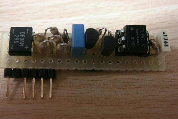
Who created
this or
other projects on this web site,
please can send me
on my
email photos
of his accomplishments?
I would like to
put it here
on-line
so that they are visible and
can serve as a
starting point for new
ideas,
different realizations or
changes, following
in this way
the spirit
of this site which
is in favor of
disclosure
and
knowledge of electronics
free of charge. Also, if you, while sending photos of your prototypes, authorize me to put on-line together with the photos at least your name and your email, you will be contacted or you can contact another user who made the same project in order to do together of constructive confrontation. Thank you in advance, Tony |
WARNING! The circuit diagrams described herein are directly connected to the mains voltage, therefore the realization, assembly etc ... are intended for experienced users and beginners.
Description of the electrical circuit:
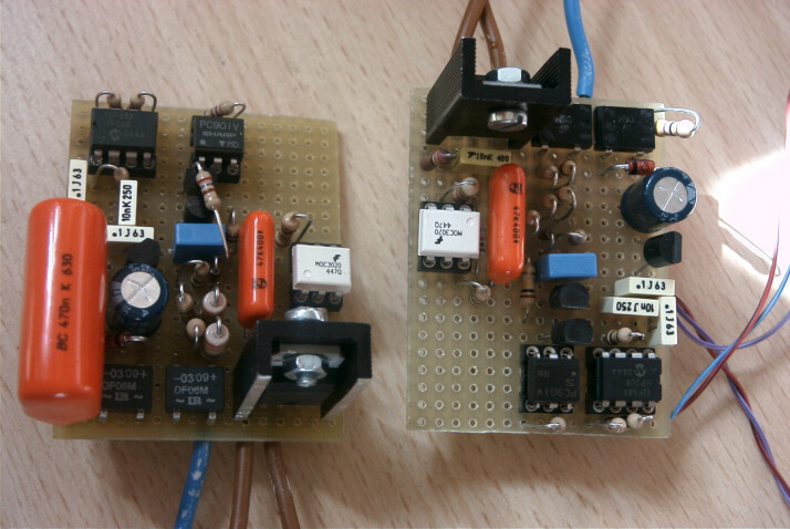
Were made several versions of this dimmer, the first version was designed with the power sections NOT connected directly to the mains but isolated by opto-couplers and power transformer.
The circuit is powered by a transformer with 6V/100mA followed by the rectifier and the regulator 78L05 always 100mA.
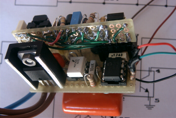
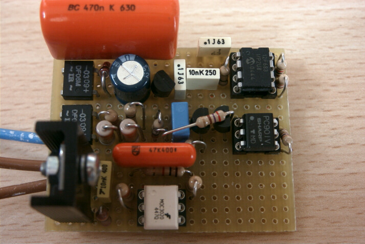
The most popular version (v. 3.1) of this circuit is the version that is powered directly from the network without power transformer with the aim of reducing cost and space in order to position the dimmer in a standard flush-mounting box type 503.
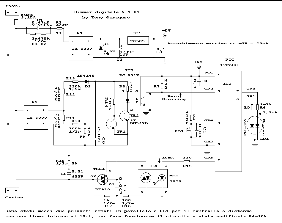
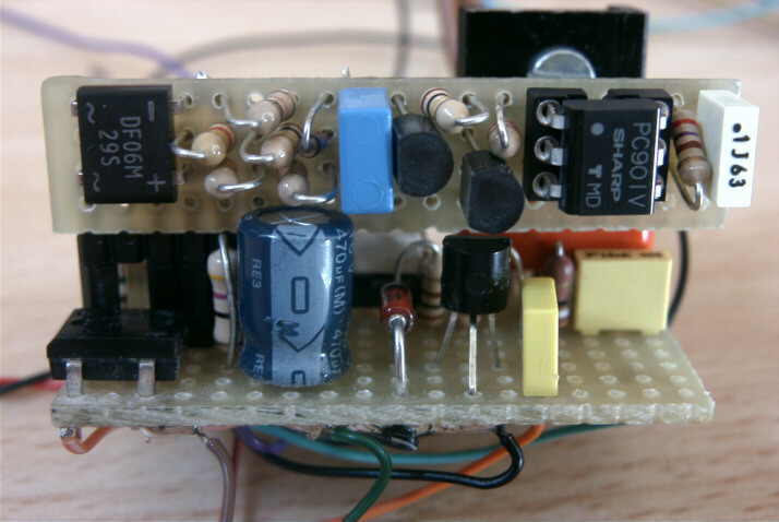
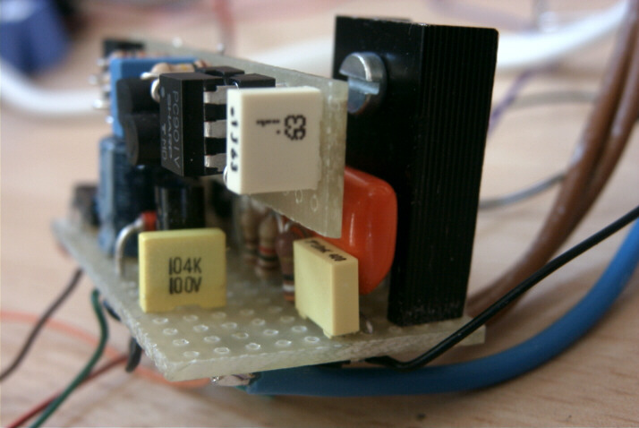
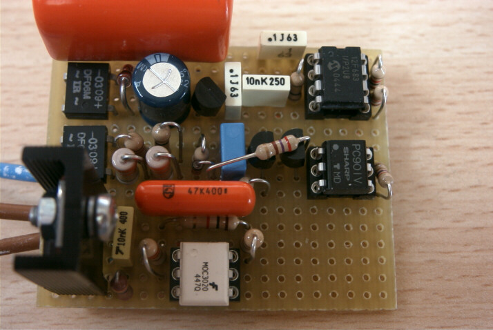
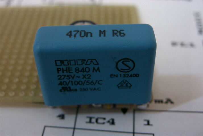
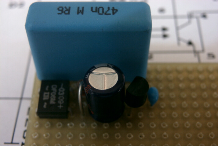
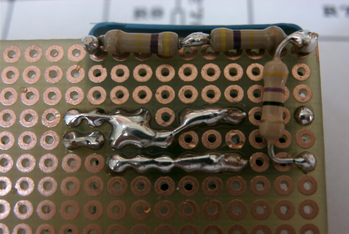
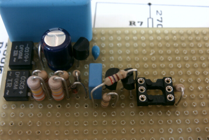
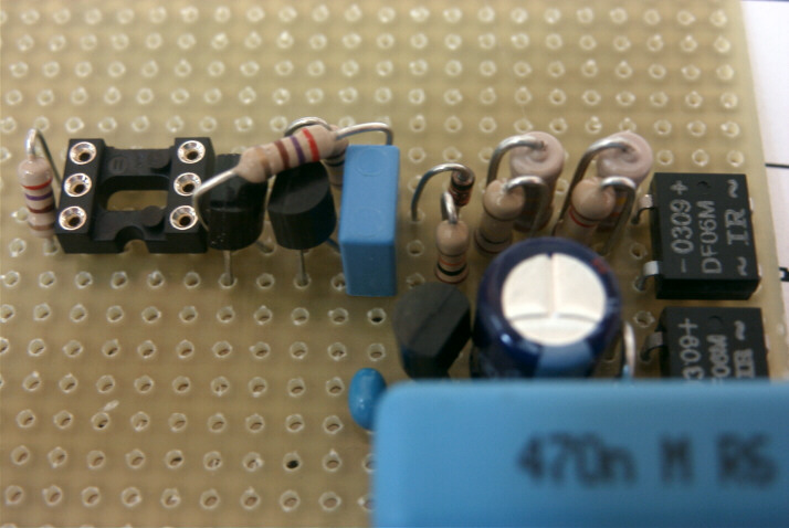
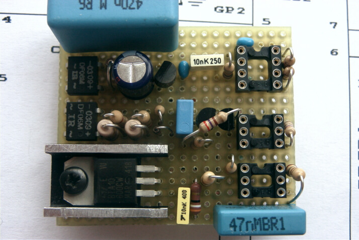
The circuit is composed as follows: Immediately after the fuse is present the capacitor 470nF class X2 with adequate insulation in order to operate the direct voltage network, in parallel to this capacitor, there are two resistors 470k, the output voltage from this capacitor passes through a resistance of 47 ohms and reaches the bridge rectifier. In output from the bridge is the zener diode from 6,8 V 1W (to stabilize the voltage and make sure that the input of the voltage regulator is not too high) followed by the smoothing capacitor from 470uF 16V and the voltage regulator 78L05 5V 100mA with a 0.1 uF capacitor.
The absorption of the circuit under all conditions does not exceed 25mA.
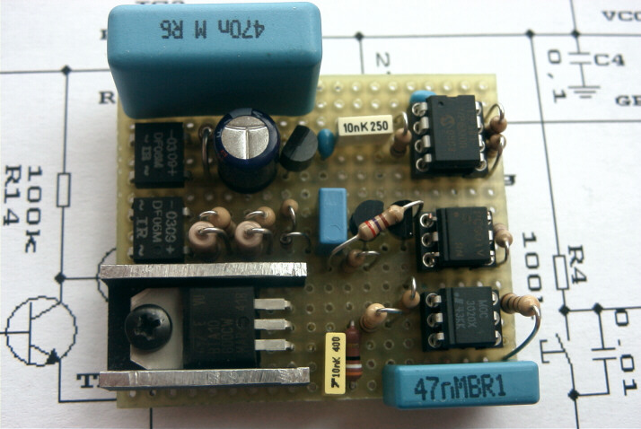
The circuit is based on a microcontroller PIC 12F683 (8 pin with 2k memory) was chosen since this micro has the internal oscillator to 8MHz, instead of the 12F675 or 12F629 that have only 1 k of memory and the internal oscillator to 4MHz.
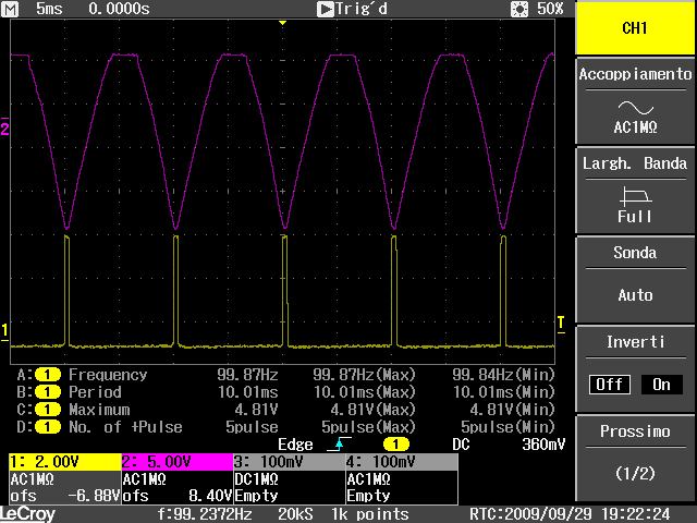
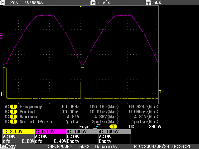
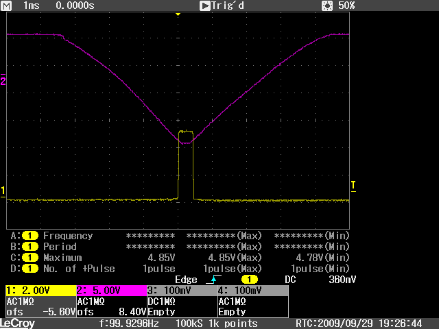
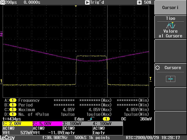
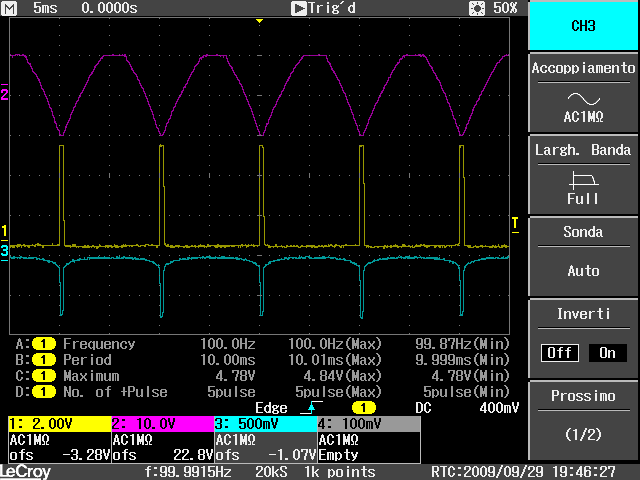
The circuit Zero-Crossing was made with a bridge rectifier directly connected to the network, followed by a resistive divider, a 1N4148 diode, a 220nF capacitor and two transistor BC547 which drive the LED of the optocoupler PC901V made by Sharp with digital output. This circuit generates the pulses in the vicinity of the zero-crossing of about 240ųS of which 120US before the zero crossing and 120uS after the zero crossing.
The program will adjust the delay on the first 120uS with the end to be more precise on the real zero of the mains voltage.
The output of this optocoupler enters the micro via pin 5 (GP2) subjected to interrupt.
The LED used is a two-color LED red / green 3mm diameter and resistors 1k limit current around 3.5 mA
The final part is composed of a photo-triac driver MOC 3020 not sensitive to the zero crossing triac BTA10 that a pilot from 10 Ampere with limiter circuit disorders composed of a capacitor C8 from 0.01 uF and a resistance of 39 Ohm 1/2W.
The pull-up resistor R4 on the button PL1 with input GP4 was set at 100k. In a couple of circuits, it became necessary to put in parallel 3 buttons for switching on and off and adjusting via a long line about ten meters, in this case was reduced by the value of the resistance R4 only 10k.
Was also conducted in a version of Dual Dimmer, in this version the capacitor C1 has been raised from 0.47 uF to 1uF. The principle of operation of this dimmer is equal to the standard dimmer described herein and differs only by the capacitor C1 and the circuit is doubled relative to the micro 12F683.
In the double dimmer version was considered the idea of using a single micro, with more out than the 12F683, however, given the criticality of the double circuit and the complete rewrite of the program as totally incompatible, it was decided to use of two 12F683.
Description of operation:
When the dimmer is switched off, the LED1 is lit (red) and serves as an indication of the position of the button management.
Briefly pressing the button for less than 400mS, it will switch from on to off or vice versa.
In the ignition phase, in order to avoid subjecting the filament of the lamp (or lamps) to a thermal shock, a ramp has been generated for the ignition gradual; zero to maximum brightness in little more than one second, and the same applies for shutdown.
When the dimmer is turned on, the button is held down for more than 400mS you enter the loop for adjusting the brightness. In fact, a ramp is generated in an infinite loop (as long as the button is pressed ...) that increases the brightness to maximum and decreases the brightness down to zero. Near the point of maximum brightness is turned on Led1 for about 1 second, then the LED is turned off and the brightness drops to zero. This waiting time causes the user has time to release the button when the dimmer is placed on the maximum brightness.
The Program:
In summary the program after initializing the micro and set the timer interrupt on GP2 and Zero, turns into a routine for handling the only button.
In dimmer mode turned off the red LED1 is on and the dimmer is switched off by pressing and releasing the button (time <400mS) causes the gradual ignition of the lamp up to the set point; That is, the dimmer is activated and consequently the 'interrupt on GP2 which intervenes with the frequency of a half-wave and that is about every 10mS with a pulse equal to 240ųS coming from the circuit for detecting the zero-crossing. Once triggered the interrupt, timer 0 is activated with delay value set to obtain the desired brightness and by the decrease of a variable is delayed innsesco triac thereby controlled the brightness of the lamp.
Routine interrupt:
This routine operates two interrupt, the interrupt coming from GP2 and the interrupt from Timer Zero.
The normal cycle of operations in this routine, provides that the interrupt is awaited on GP2 generated by the circuit for detecting the zero-crossing and that is with cadence of 10mS (every half-wave at 50Hz) and a pulse with an amplitude of about 240ųS. The pulse has a width of 240ųS namely 120ųS before the zero crossing and 120ųS after zero, this causes the triac to turn on exactly when it passes through zero must perform the SYNC routine that generates a delay equal to 120ųS, after this time, there are three possibilities:
1°) We are turning on the dimmer
1°) We are turning off the dimmer
3) The dimmer is set and is undergoing normal working
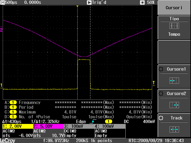
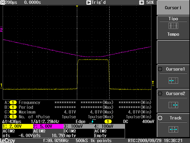
Always following the same cycle, ie after the 120ųS to turn the timer to zero with the value contained in the variable V_TMR0 (DELAY), this variable contains the delay value that ranges from zero (maximum brightness) to RAMP_MIN which is the value set for the minimum brightness. The timer is activated zero n * V_TMR0 times with a time base of 40ųs, when V_TMR0 reaches zero, the triac is triggered via the FIRING routine that generates the trigger pulse equal to 100ųS.
As previously mentioned, there are three situations that load with different values the variable V_TMR0 namely:
1°) RAMP_ON If the flag is set, it means that we are lighting dimmers and the ramp is generated power for the soft-start. The ramp of ignition has been inserted within the dimmer not only for the optical effect in pleasant see the lamp (or lamps) light up in a gradual manner, but also to protect the filament of the lamp; since the resistance of the filament in the lamp cold is about 20 times lower at the working temperature of the filament; generally the lamps will burn just at the moment the ignition, turning on the lamp instead in a gradual manner, it tends to increase the life of the lamp itself, for which, always in the function interrupt RAMP_ON if the flag is active, the variable V_TMR0 is loaded with a value that decreases automatically at each cycle shortening the delay time of ignition of the triac at each half-wave in such a way as to have the complete ignition of the lamp in a little more than 1 second.
2°) The same principle has been applied for symmetry of operation and for beauty, even during the off state; this stage is managed by the flag RAMP_OFF that operates in the opposite way by increasing the delay value loaded in V_TMR0 to each half wave until it reaches the maximum value defined in RAMP_MIN, when reached, the dimmer switch off and on again, the LED 1 red, indicating dimmer off in the dark and also the location of the power button.
3°) If the dimmer has finished the ramp up to the ignition point of predetermined brightness, starts the normal cycle, ie, charge V_TMR0 always with the same value to maintain a constant brightness and activates Timer Zero. Zero timer has a time base for which each fixed at 40ųs 40ųs V_TMR0 is decremented down to zero, when V_TMR0 is zero, the triac is triggered and since Timer zero will not fire again awaits the next interrupt from GP2 of the next step for the zero and the cycle repeats.
Change brightness:
When the ramp is finished and the dimmer switch is in normal operation, pressing and holding the button for more than 400mS will change brightness.
When you reach the point of leaving the desired brightness button, the dimmer will store level. To the next switch, the dimmer switch on the lamp always fixed at this level.
While holding down the button, the last active ramp is continued, for example, if the last time you have set the brightness of the ramp was lowering the brightness by holding down the button to set the new brightness ramp up continues from the current point at bottom of ramp and that lowers the brightness down to zero ... still holding the button, once it reaches the minimum brightness, the microcontroller reverses the ramp and begins to increase the brightness to the maximum ... always keeping the button pressed, the cycle of increasing and decreasing ramps continues indefinitely as long as the button is held down.
When the ramp which increases the brightness up to the maximum reaches the maximum, was introduced a 1 second pause, with relative lighting of the LED 2 green to indicate that the maximum brightness is reached, if the button is always kept pressed, spent 1 second, the green LED goes off and starts up the ramp to the minimum brightness.
The green led was turned on because from the visual point of view, when the lamp is at full brightness, it is very difficult to recognize when you have truly reached the point of maximum brightness, and in general, without visual signaling can be understood only when the dimmer begins the descending ramp and starts to reduce the brightness thus overcoming the point of maximum brightness. The 1-second pause is added because it has been observed that a young person waiting for an event has a reaction time of less than half a second, an elderly person passes this time ... and it did set a time of 1 second that is normally sufficient for proper setup.
Files
Data sheet bicolor
Led
Led Bicolore.pdf (122k)
Data sheet 78L05 LM78L05.pdf(686k)
Data sheet opto triac driver
MOC3020-M.pdf
(522k)
Data sheet opto triac driver
MOC3020X.pdf (68k)
Data sheet triac BTA06
bta06.pdf
(67k)
Data sheet triac BTA10
bta10.pdf
(60k)
Data sheet opto TTL
PC901V.pdf
(58k)
File .HEX per PIC 12F683
Dimmer.zip (2k)
© Copyright tony@microt.it