Clock
Kit with
PIC 18F4620
Since some
users have had difficulty in
finding some components to
achieve the clock with
PIC 18F4620
Version 3.01 to cater for
those in need we have put
together some sort of kit
containing the materials
listed below. As this is
an amateur site discharge to the
spread of electronics,
the kit is proposed to the
cost of parts plus
shipping.
The kit
includes: PIC
18F4620 already programmed,
DS1306, DS32KHZ
compensated oscillator,
EEPROM 25LC640A,
7809 and
7805 voltage regulators,
BC327, LCD
Display (standard) 4-line
20-character white,
Buzzer SMA13,
9V Rechargeable NiMh
Battery 3V Lithium
, Photoresistor,
5 small buttons
for printed circuit,
bridge rectifier, Zener
5.1 V 0.5
W, 3
Schottky diodes, 1N4004,
4 professional
sockets 40,
16, 14 and 8 pins,
clips 9V battery, 2
LEDs, 2 jumpers,
1 male strip
2.54, all resistors,
capacitors and multi-turn
trimmer, RS232
converter Module PL2303
type and the
printed circuit board. (Not
transformer and
container).
The
LCD display is always sent
with the strip
already welded
because
before sending is tested
on our
prototype for about 1 hour.
Since
there are
other versions of
this watch,
those interested in the
PCB
KIT
or
contact me
via email.
Description and Programs
Installation Instructions MontaggioKit.pdf (570k)
HEX file
for PIC 18F4620
Multilingual version 3.01
of 12/03/2013 Clock18F v3.01.rar (17k)
File
Operation Clock
Version 3.01 Funzionamento Orologio Ver 3.01.pdf (86k)
Description USB functions
Version 3.01
Descrizione funzioni USB Ver 3.01.pdf (54k)
PC
program version 3.01 Programma PC v.3.01.rar (346k)
Database program for
PC 3.1 Database.rar (15k)
Driver
FTDI adapter Driver.rar (971k)
Driver
Prolific adapter PL2303 series PL2303_Prolific_DriverInstaller_v1_7_0.zip (4Mb)
Datasheet Componenti
LCD
20x4 LCD.pdf (520Kb)
(This
datasheet is generic
because we have different
types of LCD, unless
otherwise specified the
lcd is white characters on
a black background. For other types of
lcd please contact us.
Buzzer
SMA series Buzzer SMA.pdf (1,7Mb)
PIC
18F4620 PIC 18F4620.pdf (4,1Mb)
25LC640A 25LC640A.pdf (1Mb)
DS1036 DS1306.pdf (320Kb)
DS32KHZ DS32kHz.pdf (400Kb)
7809 7809.pdf (1,5Mb)
7805 7805.pdf (260Kb)
BC327 BC327.pdf (65Kb)
1N4004 1N4004.pdf (80Kb)
SB140 SB140.pdf (78Kb)
Zener 5,1V Zener 5.1V.pdf (253Kb)
Buttons Pulsanti.pdf (302Kb)
Lithium battery BR2032V2A Batteria Litio BR2032V2A.pdf (300Kb)
9V Ni-Mh battery Ansmann Batteria 9V.pdf (253Kb)
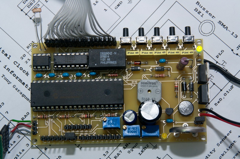
Warning:
Many photos
(below) are not made with
the PCB kit
(v.5.00) but
with an experimental version
that we use for testing.
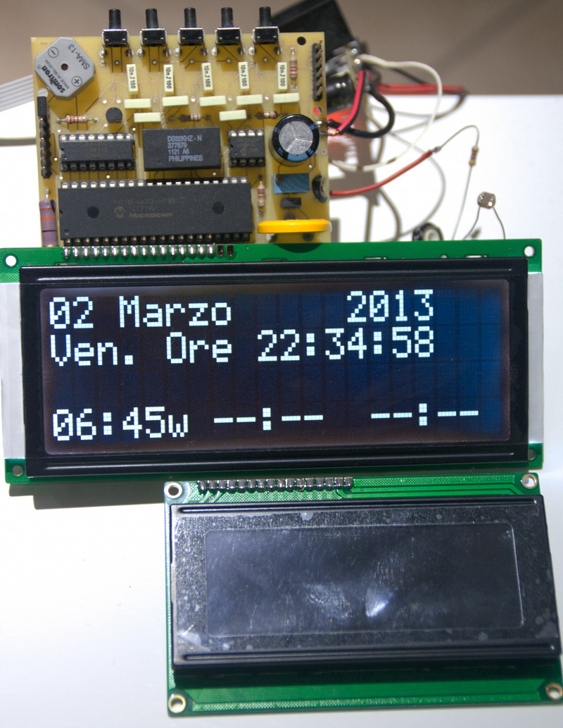
LCD Display "Big" and
Standard (white
on black)
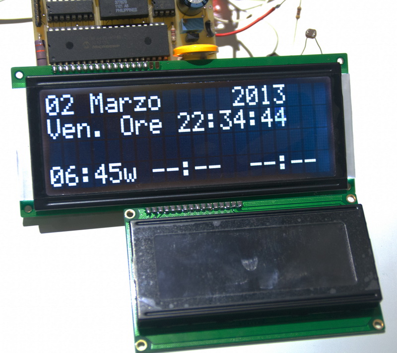
LCD Display "Big" and
Standard (white
on black)
LCD Display "Big" and
Standard (white
on black)
LCD Display "Big" and
Standard (white
on black)
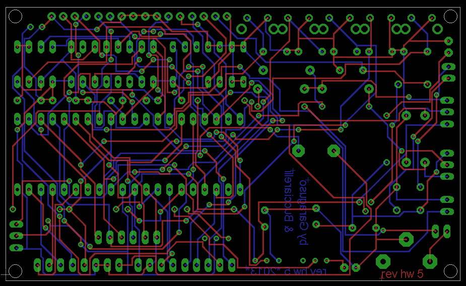
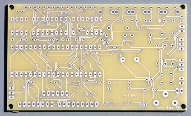
PCB
Version 5.00 (Dr.
Daniele Bucciarelli)
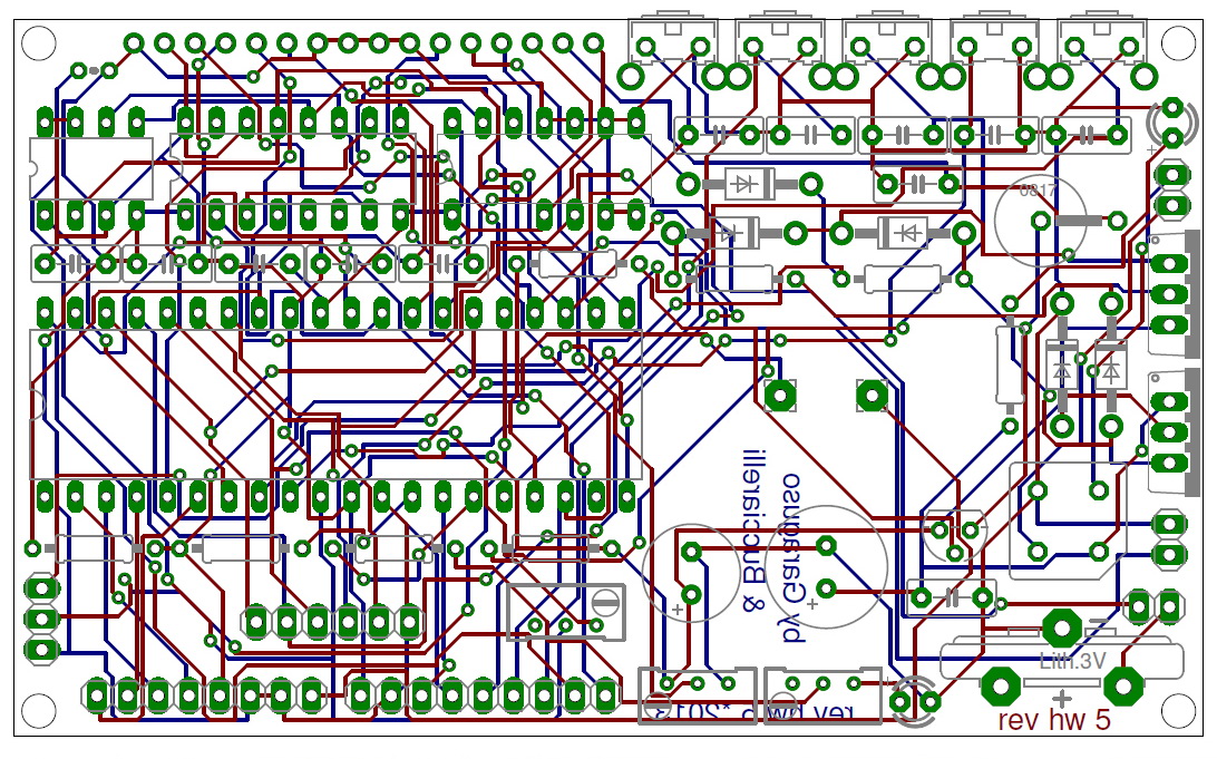
Top,
Bottom and component
location
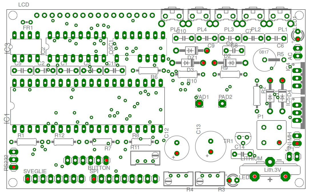
Component
names and
pin-strip, red
pin strip
are
pin 1 or
the positive
of
polarized components
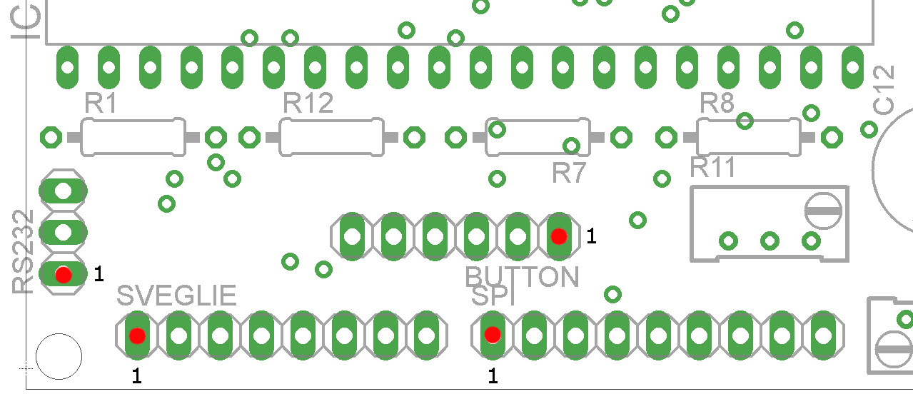
Detail strip signals
RS232:
1 GND, 2
micro TX
to RX module,
3 micro RX
to TX module
SVEGLIE:
1
Out Common
alarm clocks,
2 Alarm
Out 3,
3 Alarm
Out 2,
4 Alarm Out
1, 5 VDC
+5 V, GND 6,
7 and 8 JP2 jumper
to activate buzzer
BZ1
SPI:
1 VCC
+5 V, GND
2, 3
Reserve sensor,
4 SDA
Sensor Temperature / Humidity
(v3.10), 5
micro
SPI,
6 SPI
Clock micro,
7 SPI
Out micro,
8
micro
pin 40,
9
micro
pin 39
BUTTON: 1 GND,
2 PL1, 3 PL2, 4 PL3, 5 PL4, 6 PL6
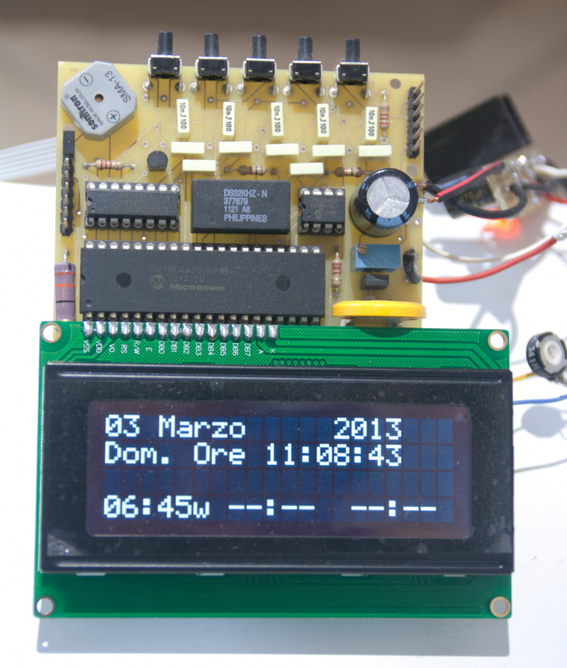
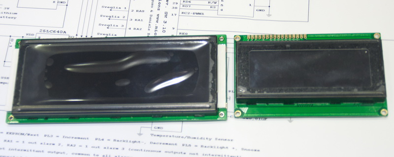
Standard LCD Display
(White on black)
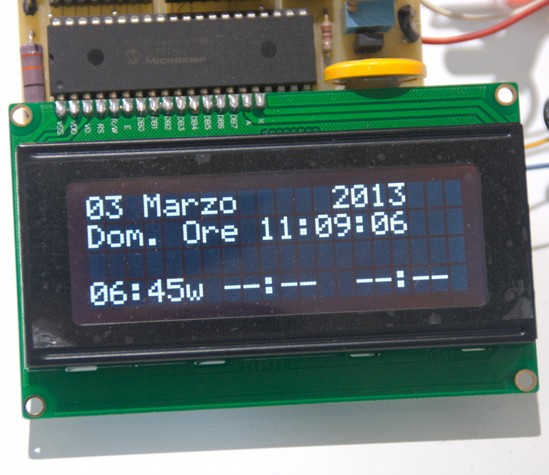
Standard LCD Display
(White on black)
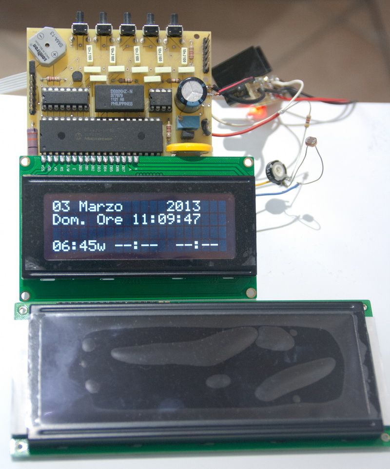
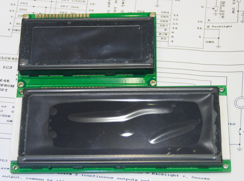
Standard
LCD Display (White
on black) compared
with "Big"
LCD
Photos
during assembly
Version 5.00 PCB component
side
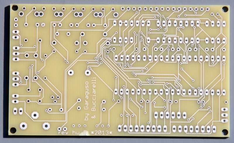
Version 5.00 PCB
solder
side
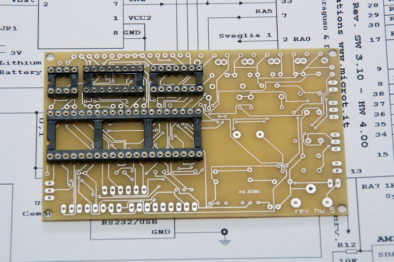
Mounting
professional
sockets
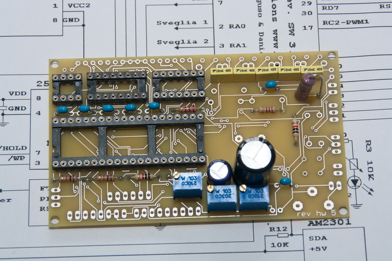
Mounting
resistors and capacitors (R10
missing
for testing
current)
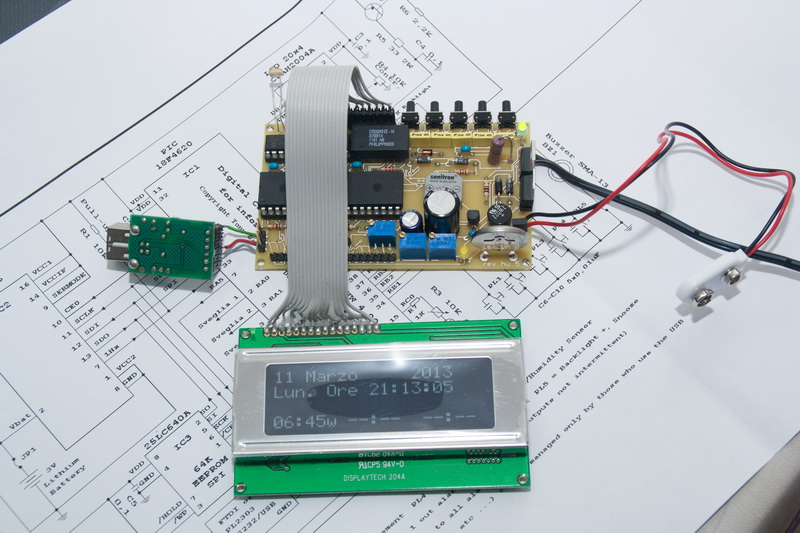
First
lighting with LCD test
View
of the set (missing
R10)
The content of these pages was released for teaching applications WITHOUT end of I make money from. For any other type of application it be able to contact me via email.
© Copyright tony@microt.it